
Version 22.00 Released
In this issue:
Version 22.00 Released!
File Compatibility
Other Resources: Technotes and Videos
Classes and Events
Current Versions
What is the Insider Release and How Do I Get It?
Version 22.00 Released
PLS is excited to announce that we have released Version 22.00. This General Release is jam packed with features and improvements.
TOWER Geometry Wizard
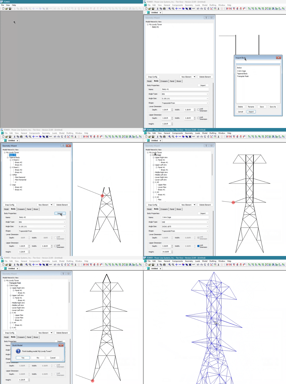
The TOWER Geometry Wizard allows you to create a new TOWER model via the menu command File / New / Geometry Wizard… using a graphical interface with tower configurations of bodies, crossarms, legs, panels and bracing patterns.
Connect one or more body segments to form the outline of your tower model. Bodies can have one of the following shapes: Trapezoidal Prism, Cage, Pyramid, and Triangular Prism. Add crossarms to model members that extend outward from the body. Crossarm shapes can be triangular, square, rectangular, or trapezoidal and may include vertical support or upper chord members. Panels are used as a container for holding one or more braces and are added to either a body segment or a crossarm. The panel contains a list of predefined bracing patterns or you can create a custom brace pattern by adding braces manually.
The entire tower model,or portions of the model can be saved in a Panel component library for reuse in future Geometry Wizard sessions. This makes creating future models easier as you can import from previously defined elements and build a tower to meet your needs quickly, as shown in the animation below.
For more information see our TOWER Geometry Wizard technical note which includes a walkthrough of an example model.
XY Planar Surface TINs and Multiple Ground TINs
Over the last several versions, we have continued to expand our TIN capabilities and Version 22.00 is no different with the support of multiple ground TINs and a new XY Planar Surface TIN.
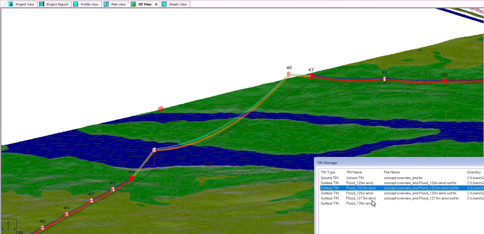
The XY Planar Surface TIN is a special kind of surface TIN which has a level plane at a constant user specified elevation found via the menu command Terrain/TIN/Create Surface TIN… and selecting the Create XY Planar TIN from the Surface Area Option. You can specify the plane’s elevation and the feature code to use for checking clearances against it. One common use for an XY Planar Surface TIN is checking clearances from varying water flood levels.
You can see this example in our XY Planar Surface TINs YouTube video.
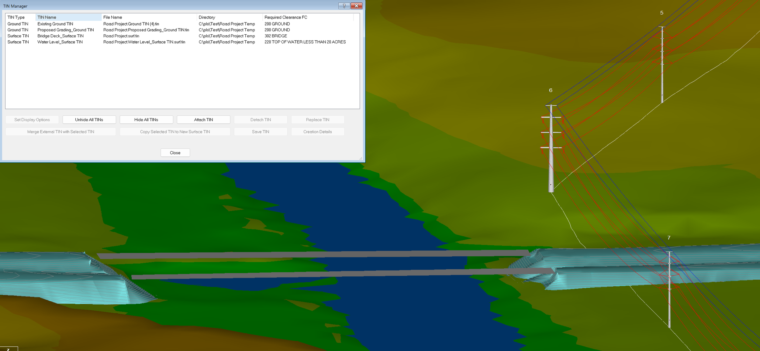
When the ground surface near your line changes, such as construction of a substation terrace, bridge, or highway ramps, it would be nice to see how that change impacts the clearances to your wires and to scope out any remediation necessary to accommodate the new earthwork. With multiple ground TINs in PLS-CADD, now you can load just the surface area that changed and perform clearance checks against it and your wires. You can create a new ground TIN the same way as before, but when you use the Terrain/TIN/Create Ground TIN… menu command, you will be asked if you would like to replace the existing ground TIN or create an additional one.
Below is an example of a proposed grading change for a bridge underneath a transmission line, where the proposed grading TIN is colored in teal while the existing ground TIN is colored by elevation. The bridge and waterway are represented by surface TINs in gray and blue respectively. You can now run Lines/Reports/Survey Point Clearances… and select either Ground TIN or both to perform your clearances checks.
Right-of-Way Checks and Foundation Footprints
The right-of-way offsets in PLS-CADD (as set in Terrain/Alignment/Display Options for P.I., Alignment, Right of Way…) can now be used to check if the structure is within the defined right-of-way corridor when running the Construction Staking Report and likewise for the conductors when running the Blowout and Departure Angle Report. These include checking the base joints, guy anchor joints, reference stakes and wire positions are inside the right-of-way boundaries.
In PLS-POLE and TOWER you can now define the foundation footprints for your structure and guy anchors via Geometry/PLS-CADD/Foundation Footprint… These footprints can be represented as circular or rectangular 2D areas.
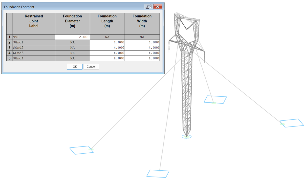
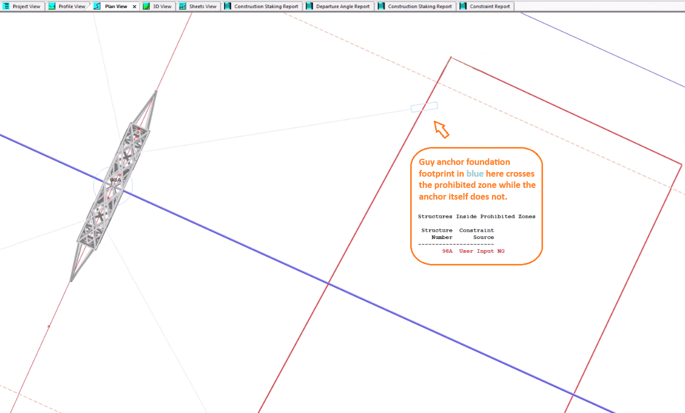
In PLS-CADD foundation footprints can be combined with the right-of-way checks to ensure they are within the boundary. The foundation footprints are also used with Automatic Spotting of structures to avoid placing structures and their foundations within prohibited or extra cost zones.
Another great addition making use of the right-of-way offsets is the ability to calculate 3D Electromagnetic Fields (EMF) directly along the right-of-way corridor using Sections/Electric/3D EMF Along Right of Way.
For more information, see our YouTube video.
Energized Zones Improvements
Since 2001, energized zones in PLS-POLE and TOWER have been used to calculate suspension swing angle limits and now you can visualize the energized zones and perform structure clearance checks against them in PLS-CADD. For the energized zones on strain insulators we have added a new flat disc shape within PLS-POLE and TOWER.
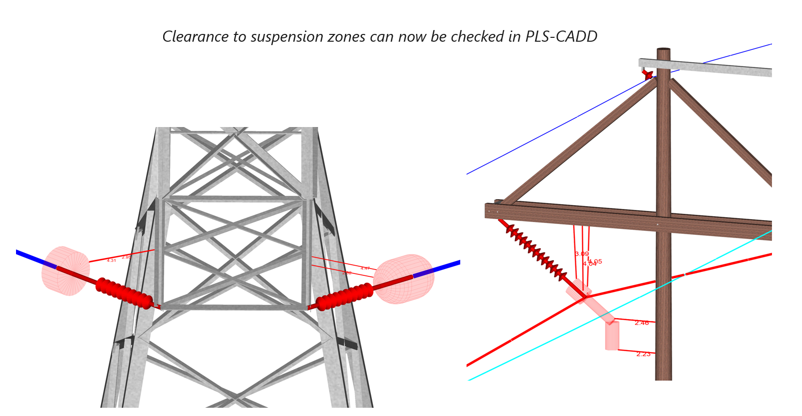
To render the energized zones in PLS-CADD, toggle the Drafting/Display Options/Show Insulator Energized Zones option, while the color can be set on the Structures tab in the Sections/Display Options… dialog. Lines/Reports/Structure Clearances… now has an option Include suspension insulator energized zones in check.
Support AI
Ever come across an error message that you’re not certain what it means or how to resolve it? Or perhaps you can’t recall which report has a particular value in it? Or you know our manuals and technical notes describe the difference between the various SAPS Finite Element levels, but don’t know where to look? These questions and more can be answered by PLS’s Help/Support AI… feature within PLS-CADD, PLS-POLE, and TOWER applications.
Support AI harnesses the power of Large Language Models (LLM) and Retrieval Augmented Generation (RAG) technologies with Power Line Systems' vast array of detailed manuals, technical notes, YouTube videos, and responses to common technical support questions curated and vetted by our team to provide you answers to your questions.
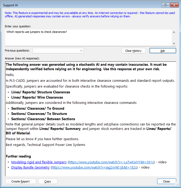
Available through the Help/Support AI… menu, the response to your question about PLS software will reference relevant menus and reports as well as sections of the manuals and can provide links to our technical notes and videos related to your topic for further reading. Like with all AI tools, you should always verify the accuracy of the response.
Only information that you provide in the question box is used by AI to answer your question. No model data is ever transmitted to AI. If you have a specific question about your model, you can always contact our technical support team at support@powerlinesystems.com and we would be happy to help.
For more information, please see our YouTube video.
Model Context Protocol (MCP) Server
Version 22.00 introduces another AI feature to our software with addition of a Model Context Protocol (MCP) server. A MCP server allows you to connect any AI agent of your choice to our application and you can query your AI agent about your model and can even automate certain tasks on your model.
The MCP server within PLS-CADD allows you to use your AI agent to query information that is available in PLS-GRID.The MCP server has read-only access to projects, structures, spans, reference files and reports. This allows you to create complex reports combining information from multiple sources faster than creating by hand.
The MCP servers within PLS-POLE and TOWER allow you to use your AI agent to query information within your model as well as modifying existing models and creating new ones. This provides you a powerful way to automate many repetitive tasks such as adding or moving arms, insulators, guys, equipment and framing elements while also being able to analyze the model.
The MCP servers must be explicitly enabled and run locally on your system with the AI agent of your choice. Choose an AI agent that meets your organization’s data and privacy requirements. As with all AI tools, you should always use your engineering best judgement when reviewing the output from AI.
For more information, please see our YouTube videos and our technote:
Version 22.00 continues our long tradition of meeting client requests for additional features and functionality while also supporting the latest industry standards. Some notable features are highlighted below:
PLS-CADD
"Help/Support AI" uses an LLM to answer user entered questions using PLS documentation, technical notes, and selected PLS Technical Support answers.
PLS-CADD can now function as an MCP server providing AI read-only access to PLS-GRID data such as projects, structures, wires, and reports.
"Drafting/Display Options/Show Insulator Energized Zones" to graphically render the energized zone defined in PLS-POLE and TOWER models.
Added the option 'Include suspension insulator energized zones in check' to "Lines/Reports/Structure Clearances..."
"Structures/Automatic Spotting/Generate Allowable Spans / Interaction Diagrams..." automates generation of M1 or M2 structure files from M4 files, with options for creating all heights/classes of PLS-POLE structures.
"Sections/Electric/3D EMF Along Right of Way" calculates EMF along the project's defined right of way.
Added an 'Inside Right of Way' check to "Lines/Reports/Construction Staking Report..." and "Lines/Reports/Blowout and Departure Angle Report..."
Added "Drafting/Display Options/Show Foundation Footprint" to show any foundation footprints configured by PLS-POLE or TOWER structures.
"File/Export/3D Tiles (Cesium)" exports the 3D geometry of the entire project in the Cesium 3D Tile format.
Added support for exporting the entire project geometry in the Cesium 3DTile format to support the PLS-GRID web client's Cesium 3D Viewer.
Added 20 Section Comment columns to "Sections/Table..." which function similar to Structure Comment columns. These Section Comment fields can be used for Section Labels in "Drafting/Structure and Section Labeling/Sheet Profile View..." and "Drafting/Structure and Section Labeling/Grid View..."
Added support and options to "Terrain/Automatic Model Builder (AMBER)..." for strain and suspension insulators, skip-span connections, alignment-based or XY structures, separate weather cases for each circuit, specifying sagging conditions, user defined alignments, and specifying multiple feature codes for wire attachments.
Added the "File/PLS-GRID/Batch Export to GRID" command to update the GRID Map data, including generating 3D Tiles, for several projects at once without having to check out and check in each one.
"Drafting/Inset Views/Build Inset Report View/Link CSV File..." adds the specified CSV file to the Reference Manager and builds an inset report view with the contents of that file which can update as the file is updated.
"Drafting/Annotation (Program-Generated)/Configure..." provides new options for Auto Add Dimension Lines to offset small dimension measurements or use oblique lines instead of arrows.
PLS-POLE / TOWER
"Help/Support AI" uses an LLM to answer user entered questions using PLS documentation, technical notes, and selected PLS Technical Support answers.
PLS-POLE and TOWER can now function as an MCP server providing AI access to structure models.
Added energized zone end cap shape option (Spherical or Flat) to "Components/Insulators/Strain Properties…"
"Geometry/PLS-CADD/Foundation Footprint..." defines a circular or rectangular region around foundation joints that PLS-CADD can check against.
"View/Display Options/Show Foundation Footprint" shows any foundation footprints with the structure geometry.
"Drafting/Inset Views/Build Inset Report View/Link CSV File..." adds the specified CSV file to the Reference Manager and builds an inset report view with the contents of that file which can update as the file is updated.
Added the "File/Batch Modify..." option 'Consolidate Components Files' that applies the source model's component files to all selected models while adding any missing (or different) referenced properties from the target models to those component files.
Improved performance of certain types of calculations. Can result in up to 10% faster overall analysis.
"Drafting/Annotation (Program-Generated)/Configure..." provides new options for Auto Add Dimension Lines to offset small dimension measurements or use oblique lines instead of arrows.
Added new Annotation Types for oblique lines and offset dimension text to the Edit Annotation table.
PLS-POLE
"Geometry/Framing/Move Selected" to graphically select and move multiple frame sets simultaneously.
Added 'Auto Set Azimuth' column to "Geometry/Vangs..." to automatically adjust the azimuth to a connected guy or insulator.
Improved "Drafting/Annotation (Program-Generated)/Auto Add Dimension Lines" to work with elements within a frame set.
TOWER
Added "File/New/Geometry Wizard..." interactive feature to create geometry of a new tower model.
Added 'Summary of Maximum Usages by Section' and 'Summary of Maximum Usages by Section Super Set' to "Model/Run" results.
Added "General/General Data..." option 'Coalesce collinear corner diagonals'. The default checked state behaves the same as before. When unchecked, TOWER will still coalesce crossing diagonals, but NOT corner diagonals.
When exporting models, the Family Manager now converts machine generated parts from body and leg extensions into user generated parts so they are preserved.
PLS-GRID
Added a new Cesium GRID View which shows a 3D view with satellite imagery of all projects that have 3D Tile data uploaded to the PLS-GRID server.
Added 'Temperature and Wind' to the Web Client Map Layers options which shows predicted conditions from the US National Weather Service at the specified day and time at structure locations on the PLS-GRID Map.
Allow batch photo uploads from the web client.
Added XML as an option to the "Download Spreadsheet" command accessible through the Project Files page, the GRID Map context menu when snapped to a project, and the GRID Map area select tool.
Added 'Project Manager' privilege for "Manage User Access" which is similar to 'Admin' except it does not have access to updating, restarting, or turning off the server or viewing the endpoint log.
Added "McpEnabled" option to client.json to control whether AI tools can use PLS-GRID data through PLS-CADD acting as an MCP server. This is off by default.
Several significant performance improvements throughout.
What About File Compatibility?
PLS applications will always save files in the most compatible format based on the features used by the model. If you are not using new features that require file format changes, the software will automatically save to an older version.
Models saved are backwards compatible with versions 20.01 and 21.01 unless specific new features are enabled at the time of the save. Those new features that require file format changes are always listed first in the version change logs. These changes are conditional, meaning if you remove use of those features and save the model, it will save to an older file format that your client with an older version can work with.
When saving a model that requires a newer file format not supported by earlier versions of the application, a notification message will be shown with the specific feature that required the newer version. This notification helps you decide if you want to turn off that new feature to ensure backward compatibility, putting you in full control of file compatibility.
As always, the latest version of the software will open any models created by an earlier version.
For more information on File Compatibility, please see our white paper that goes into more detail.
Other Resources: Technotes / Videos
Our team has been busy expanding our library of technical notes and videos. We hope that this supplemental feature documentation makes your use of the software more pleasant and productive. Please let us know if you have a topic that you think would benefit from a technical note or video. Here are our latest efforts:
Technical Notes
Videos
Current Versions
The current General Release version of our software is 22.00 and Insider Release is version 22.04. These versions support the 64-bit editions of Windows 11.
You can update your PLS applications via "Help/Download Upgrade..." or you can email us and we'll be happy to send you a new download link.
Your feedback is vital to our development process as it helps shape our software, ensuring we provide you the best experience and features that meet your needs and expectations. Please send us any suggestions, bugs or other feedback via email at support@powerlinesystems.com
If you have any colleagues that might be interested in joining our Insider Release Program, please have them email us at support@powerlinesystems.com.

How Do I Get the Insider Release?
Did you know that you can try the latest PLS features before anyone else? With our Insider Release Program, you can always have the latest and greatest software at your fingertips.
Every 3-4 weeks, Power Line Systems publishes a new Insider Release packed with the latest improvements and new features. Client feedback from these releases are a vital part of our development process, allowing us to quickly respond to your needs and experiences. Joining our Insider Release Program and giving feedback is the best way to shape new features to ensure that they meet your expectations.
Getting into the Insider Release Program is easy. Just email support@powerlinesystems.com requesting a download link for the Insider Release and our team will be happy to send you the link and instructions for installing.
Once you've installed the Insider Release, the software will notify you automatically when a new version is available and gives you the option to install it, keeping you up to date with the latest version with the latest features as they are developed.
If you are already on the Insider Release, but don't know if you have the latest installed, you can check by launching any of our applications and navigating to Help/Download Upgrade... and follow the onscreen prompts.
If you are not receiving these newsletters directly and would like to do so, please register at PLS Mailing List.
