TOWER
Analysis and Design of Steel Latticed Towers Used in Transmission and Communication Facilities
TOWER is a powerful and easy to use Microsoft Windows program for the analysis and design of steel latticed towers used in electric power lines or communication facilities. Both self-supporting and guyed towers can be modeled. The program performs design checks of structures under user specified loads. For electric power structures it can also calculate maximum allowable wind and weight spans and interaction diagrams between different ratios of allowable wind and weight spans.
TOWER is the result of more than 35 years of evolution from our earliest structural analysis programs. During our years supporting it we have received comments and suggestions from hundreds of utilities, fabricators and consultants around the world, which we have used to refine our algorithms, user interface and program design. The result is a powerful and comprehensive design tool with unsurpassed reliability and ease of use.
Comprehensive Structure Modeling
TOWER structures are collections of the following components:
Angle Members
Solid Round Members
Pipe Members
Bolts
Guys
Cables
Equipment (user defined items like antennas, cable conduits, ladders etc.)
Insulators (clamp, strain, post, suspension, 2-parts)
Building a structure is as simple as defining the overall outline geometry of the tower, selecting intermediate joints and then lacing members or other components up between these joints. You are free to mix and match the various members and components at will. This gives you the power to create arbitrarily complex structures, including lattice box structures used in many older substations.
Component libraries define the size, weight, strength and other properties of your bolts, guys, members and other equipment. You can create these libraries yourself or use libraries provided by your suppliers. Using libraries of standard components greatly enhances your productivity by significantly reducing the amount of input, which also reduces the chance of error.

Simple and Powerful Finite Element Analysis
TOWER takes the pain out of finite element analysis. A lattice structure modeled in TOWER is input as a collection of elements and the connections and bracing properties for each member. TOWER takes advantage of symmetry in a structure in both joint and member generation, duplicating symmetrical joints and members about either axis, both axes and even in a triangular format found in many communication structures. Even very large or complicated structures can be modeled in TOWER in just a few hours.
A special version of our SAPS finite element analysis engine powers TOWER. We designed SAPS specifically for solving complicated transmission line and guyed communication structure problems that other finite element programs couldn't. For nearly 30 years of production use SAPS has proven to have one of the best nonlinear cable elements available anywhere.
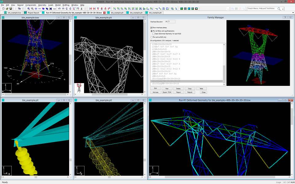
TOWER is capable of performing both linear and nonlinear analyses. Nonlinear analysis allows you to see P-Delta effects, to detect instabilities, accurately model tension-only members and perform reliable buckling checks. TOWER models guys, cables and 2-part insulators as 3-d cable elements. This sophisticated analysis works even when the elements have large displacements, as is the case with the cross rope structure pictured above.
ASCE-10 and Other Code Checks
Once TOWER has calculated the forces experienced in the different members and components of your structure, it compares them against automatically calculated code capacities for the code you have selected. The results of these checks are available in text reports, spreadsheets or color-coded graphics.
ASCE-10, ECCS, EN50341 (CENELEC), AS 3995, BS 8100, and other international codes can be used to check the structure. Members are checked against their ultimate strength in accordance with the code selected, with overstressed members easily identified graphically and in the output reports. TOWER performs your choice of linear or exact nonlinear analysis. The TOWER manual describes how these checks are implemented and details the assumptions made.
In addition to these code checks, TOWER can calculate pairs of allowable wind and weight spans, or better yet, determine entire interaction diagrams between the allowable wind and weight spans. Optimum spotting performed with these interaction diagrams will result in a more economical solution than traditional spotting with just a single, or a few, wind and weight span pairs.
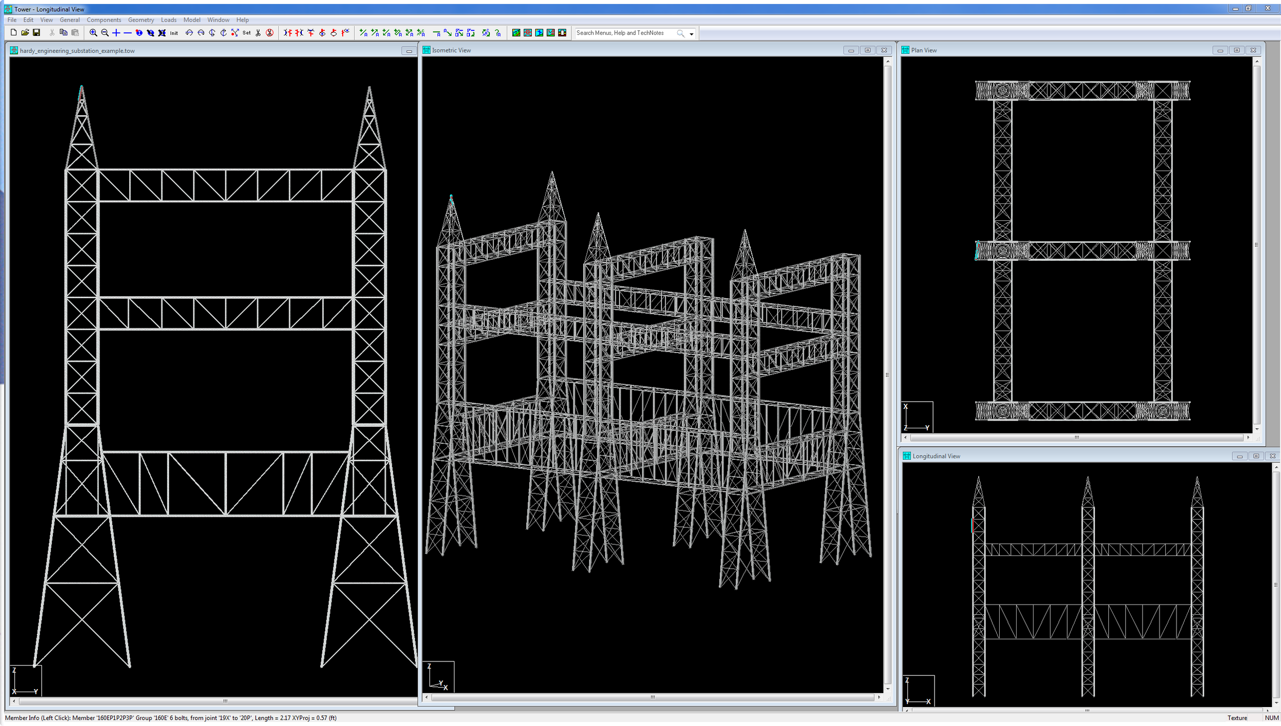
Intuitive Graphical User Interface
TOWER makes extensive use of 3-d graphics to help you visualize your structure. We render all elements in 3-d and let you view the structure from any direction making modeling mistakes immediately apparent. If you see a mistake you simply click on it to edit the problem joint, member, or component.
After an analysis, elements are color-coded based on their utilization with overstressed elements graphically shown in red. Of course, these elements can be edited with a single click. Overstressed elements are also colored red in text and spreadsheet reports.
Just as important as the graphical feedback are the many sanity checks TOWER makes on your input data. In the course of reviewing thousands of problematic structure models we have identified many common modeling errors. TOWER automatically detects these errors and flags questionable input to save you time.
Interoperability
While TOWER is a stand-alone program it's open design allows it to easily interface with other programs.
TOWER provides a well defined XML output file and hooks that enable pre and post-processors to be connected to the program making it the ideal engine of your custom lattice tower analysis process.
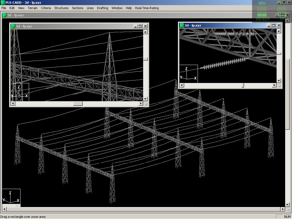
Towers shown rendered inside PLS-CADD (click to view larger image)
Users of our PLS-CADD line design program can use TOWER to prepare allowable wind and weight span or interaction diagram files for optimum spotting. They can also take TOWER structures and spot them in a line. PLS-CADD can calculate the loading on a structure at a particular location and display the results of a TOWER check with those loads.
TOWER results are presented in a combination of graphical views, spreadsheets and text reports. All of this information can easily be exported to other programs. Graphical results can be saved in DXF files compatible with most CAD systems. Spreadsheet results may be saved in an XML file, pasted into spreadsheet programs or exported to ODBC compliant databases. Text results can be customized by the user and saved to files or pasted into word processing programs.
Summary
TOWER provides all of the capabilities a structural engineer requires to analyze or design lattice transmission, substation, or communications structures. It does so using a simple easy to use graphical interface that rests upon our time tested finite element engine. Regardless of whether you want to model a simple 69 kV lattice tower, a 500 kV double circuit tower, or a 600' guyed communications tower, TOWER can handle the job simply, reliably and efficiently.
If you would like more information about TOWER please contact us.
Summary of Features
A Microsoft Windows 10 or 11 (x64) environment that lets you:
Specialized program for the analysis and design of steel latticed towers
Extreme ease of input through interactive menus
Linear and nonlinear finite element analysis options
Databases of steel angles, rounds, bolts, guys, etc.
Automatic generation of joints and members by symmetries and interpolations
Automated mast generation (quickly builds model for towers that have regular repeating sections) via graphical copy/paste
Creates and reuses Leg and Body Extensions so that an entire structure family can be designed in one model
Steel angles and rounds modeled either as truss, beam or tension-only elements
Guys are easily handled (modeled as exact cable elements with nonlinear analysis)
Automatic handling of tension-only members
Automatic distribution of loads in 2-part suspension insulators (v-strings, horizontal vees, etc.)
Automatic calculation of tower dead, ice, and wind loads as well as drag coefficients according to:
ASCE 74-1991, 2009
NESC 2002, 2007, 2012, 2017
IEC 60826:2003, 2017
IS 802 : 1995, 2015
ISEC-NCR-83
EN50341-1:2001 and 2012 (CENELEC)
EN50341-3-2:2001 (Belgium NNA)
EN50341-3-9:2001, EN50341-2-9:2015, 2017 (UK NNA)
EN50341-3-17:2001 (Portugal NNA)
EN50341-2-22:2016 (Poland NNA)
AS/NZS 7000:2010, 2016
ESAA C(b)1-2003 (Austalia)
TPNZ (New Zealand)
REE (Spain)
SP 16.13330.2011 (SNiP Russia)
Minimization of problems caused by unstable joints and mechanisms
Automatic bandwidth minimization and ability to solve large problems
Design checks according to (PLS can add strength checks for other standards):
ASCE 10
AS 3995 (Australian Standard 3995)
BS 8100 (British Standard 8100)
EN50341-1 2001 and 2012 (CENELEC, both empirical and analytical methods are available)
EN50341-2-9:2015, 2017 (UK NNA)
ECCS 1985
NGT-ECCS
PN-90/B-03200
EN50341-2-22:2016 (Poland NNA)
SP 16.13330.2011 (SNiP Russia)
EDF/RTE Resal
IS 802 (India Standard 802)
Design summaries printed for each group of members
Easy to interpret text, spreadsheet and graphics design summaries
Automatic determination of allowable wind and weight spans
Automatic determination of interaction diagrams between allowable wind and weight spans
Capability to batch run multiple tower configurations and consolidate the results
Automated optimum angle member size selection and bolt quantity determination
Tool for interactive angle member sizing and bolt quantity determination
Capability to model foundation displacements
Can optionally model foundation stiffness
Detailed user's manual with examples
On-line/electronic user's manual linked in to provide context sensitive help (also available in French)
User interface available in English, French and Spanish
Imperial or SI (metric) units
Powerful graphics module (stress usages shown in different colors, rendered angles)
Graphical selection of joints and members allows graphical editing and checking
Towers can be shown as lines, wire frames or can be rendered as 3-d polygon surfaces
Can extract geometry and connectivity information from a DXF CAD drawing
CAD design drawings, title blocks, drawing borders or photos can be tied to structure model
XML based post processor interface
Steel Detailing Neutral File (SDNF) export to link with detailing packages
Can link directly to line design program PLS-CADD
Automatic generation of structure files for PLS-CADD
Links
Information for Prospective Clients
Frequently Asked Questions Regarding the Purchase of PLS Software
Technical Notes: You can find many technical notes here which discuss topics such as available loading methods, applying NESC insulator requirements, importing and exporting data, weight spans, customization and localization, etc.